Serial access
The install runs at the serial console of the control board, because the factory firmware offers no SSH. This page tells you the three ways to reach that console: the Micro-USB port that early machines have, the OpenGlow serial adapter, or a soldered FTDI cable.
1.8 V only
The console domain of the control board is 1.8 V. Never connect a 3.3 V or 5 V adapter to these test points. Anything higher than 1.8 V irreversibly destroys the control board.
The console settings are 115200 8N1 in every case. Select a color terminal with UTF-8 encoding for the best experience from ForgeFIRM (PuTTY works well). The console test points and their nets are in Buses.
The console login is root with no password, on the factory firmware and
on ForgeFIRM alike. On ForgeFIRM root works at the console only: SSH refuses
root, and the panel's account opens SSH
(The control panel).
Machines with a Micro-USB port
Older Glowforges have a Micro-USB serial port connector on the control board: J13, in the lower left of the control board in the test-point picture further down this page. If you are fortunate enough to have one of those units, plug it into your PC. It is a standard FTDI FT230 serial-to-USB adapter, and the driver is included in most operating systems.
The OpenGlow serial adapter (BBPSAv1)
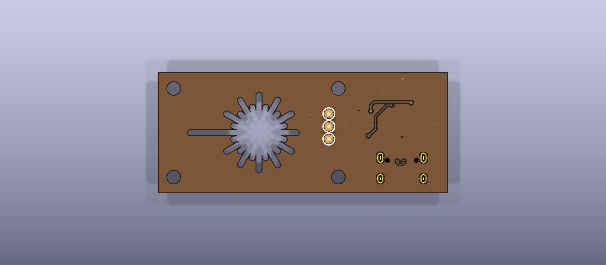
The OpenGlow serial adapter is a USB-C serial-console adapter for the Glowforge Basic, Plus, and Pro control board. It mounts onto the board with snap-in supports and contacts the i.MX6 console test points (D3B, D3D, GND) through three spring-loaded pins: no soldering to the machine.
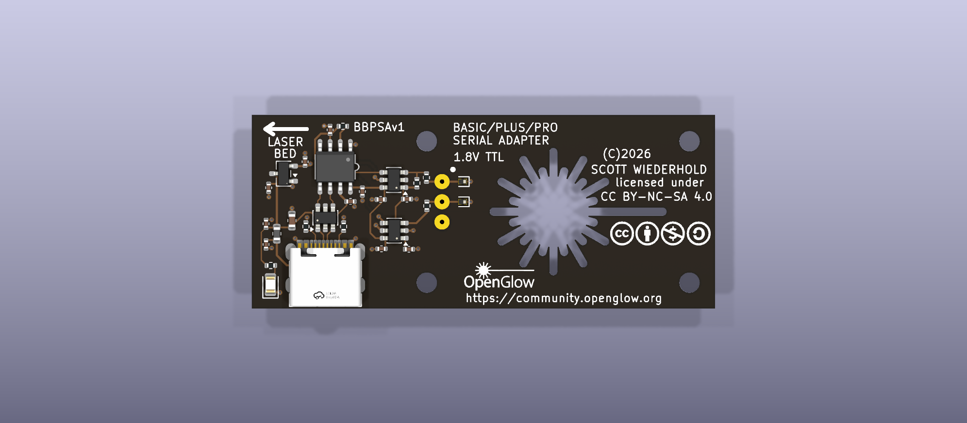
It exists to give ForgeFIRM users a console on the factory control board without the two problems of the soldered FTDI-cable approach: the solder joints on fragile test points, and the machine refusing to boot whenever the cable is unpowered.
What it does
- USB-C to 1.8 V TTL serial, 115200 8N1, built on the WCH CH9101N.
- Safe to leave mounted. The target-facing pins go high-impedance (2 µA or less) when the adapter is unpowered, so the machine boots normally with the adapter in place and the USB cable unplugged. Two SN74LVC1T45 level translators with VCC isolation are what make that true.
- 1.8 V only on the machine side, with 1 kΩ series resistors and GND-referenced TVS diodes on both signal pins.
- Single board, 58.2 × 24.35 mm, JLCPCB-assembled except for the three hand-soldered pogo pins.
DESIGN.md in the adapter repository is the full circuit description: the target interface, every net, why the values are what they are, the mechanical design, and the bring-up checklist.
Status
The electrical design is complete, and the fabrication files in the
repository's jlcpcb/ directory are the files submitted for manufacture.
Confirmation of the fit to the control board (the mounting-hole pattern, the
pin registration on the test points, and the standoff length) on
manufactured units is planned.
Installation
The installation notes, with photos of an actual install, are planned. They
cover the snap-in supports, the orientation (the LASER BED arrow and the
pin-1 dot), the pre-mount checks from DESIGN.md section 10, and the
host-side driver setup. Two things do not change:
- Never connect a 3.3 V or 5 V adapter to these test points. The console domain is 1.8 V; anything higher destroys the control board.
- Orientation matters. Fitted end-for-end, the adapter's ground pin lands on the i.MX6's TX output. Confirm which end is ground with a meter before the first power-up.
Host drivers
The CH9101N uses WCH's CH343 driver family: CH343SER on Windows and
macOS, ch343ser_linux on Linux. It can also enumerate as a plain CDC-ACM
device. The chip reports a unique serial number, so a udev rule can give a
specific adapter a stable device name.
Building one
- Order the board from
jlcpcb/production_files/(Gerber zip, BOM, CPL) with SMT assembly; all top-side parts are in the JLCPCB parts library. - Hand-solder three Mill-Max 0906-3-15-20-75-14-11-0 spring pins from the top so they protrude from the bottom.
- Fit four Richco DLCBST-3-01 (4.8 mm) snap-in board supports in the corner holes.
- Run the bring-up checklist in DESIGN.md section 10 before the adapter goes near a machine. Step 5, the unpowered-leakage measurement, is the one that proves the adapter is safe to leave mounted.
Regenerating the artwork and the schematic images needs Python 3 with
shapely, svgpathtools, ezdxf, and matplotlib, plus kicad-cli from
KiCad 10; each script in artwork/ documents its own usage in its header.
The hardware design and everything in the adapter repository are licensed under the Creative Commons Attribution-NonCommercial-ShareAlike 4.0 International license (CC BY-NC-SA 4.0).
A soldered FTDI cable
If you have neither of the above, you can solder a cable to the test points. First, you will need a soldering iron. No getting around that one. Next, you need an FTDI TTL-232RG-VREG1V8-WE USB to serial port adapter. It is important that you get the 1.8 V model. If you get a 3.3 V or 5 V version you will irreversibly destroy your control board. You can purchase this directly from FTDI, Amazon, or most electronic supply shops.
When you receive your adapter, you'll need to prep it. Only three of the lead wires are required. Trim the others, to unequal lengths, lest they short out when you heat-shrink or tape them up.
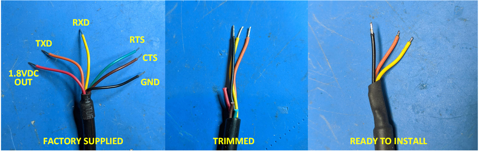
You will be connecting to the microprocessor's serial console port test points: RXD: D3B, TXD: D3D.
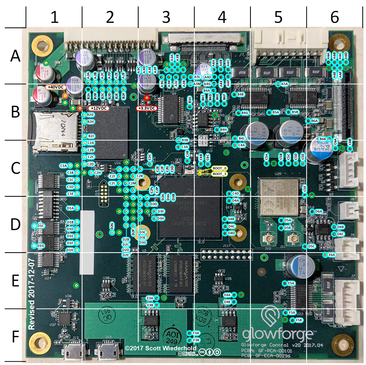
Solder the ground wire first, to the ground pad located to the upper left of the microprocessor (see the picture below). Clip the leads for TXD and RXD to no longer than a millimeter before soldering. This helps to avoid unwanted contact with surrounding items.
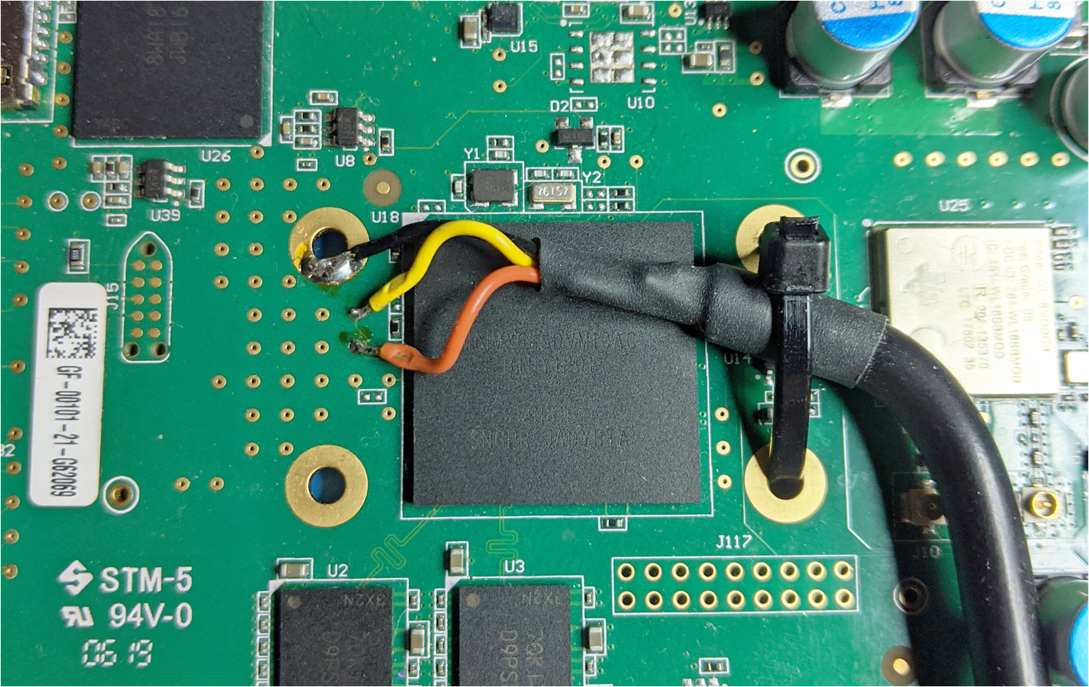
After you've soldered all the leads, secure the cable to the PCB with a tie wrap, as pictured. This is important. The test points will not stand much mechanical stress, and will rip off the board easily. Don't worry, if this happens to you, they are still accessible from the bottom of the board: a second chance.
From there, connect the USB cable to your computer and fire up your favorite terminal. The serial settings are 115,200 8N1.
Keep a soldered adapter powered
You will need to keep the serial port adapter powered on at all times when you are operating the Glowforge. If it is not powered, it draws down the 1.8 V bus on the control board and prevents it from booting. If you do not always have a computer nearby, plug it into a USB charging adapter.